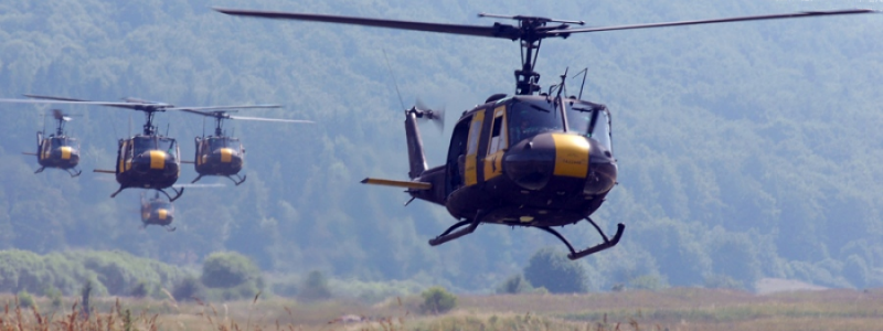
Having modeled aircraft flown by our grandfathers in World War I (the Sopwith Pup) and our fathers in World War II (the FM2), we wanted to model an aircraft flown by our generation in Vietnam. This created an unexpected challenge because the most common aircaft used in Vietnam was not an airplane, but a helicopter - the ubiquitous Huey. Of the 11,827 helicopters that served in Vietnam, 7,013 were Hueys. Of these, 1,925 were lost in combat, while 1,380 were lost in operational accidents.
Modeling a helcopter has proven to be difficult. Since a Huey does not perform loops or rolls, we did not have to use complex routines to compute the rotation of the helicopter. However, the aerodynamics of a helicopter are complex. An airplane flies in one direction and the performance can generally be simulated using a few simple formulae. However, a helicopter flies in many directions. The formulae which apply to airplanes do not necessarily apply to helicopters. And the formulae which apply to helicopters often prove irrelevant at the boundaries.
My objective is to create a helicopter flight simulation that:
- Is easy to fly.
- Generally simulates the performance of a Huey.
This has been a challenge. By nature, a helicopter is not easy to fly. Merely learning to hover takes most pilots 6-8 hours.
So, by necessity, the simulation will contain many simplifications. Our operative assumption is that you are taking on the personna of a fully trained pilot who knows how to handle the many of the complexities, such as maintaining altitude. We will try to highlight the areas in which the simulation varies from real life.
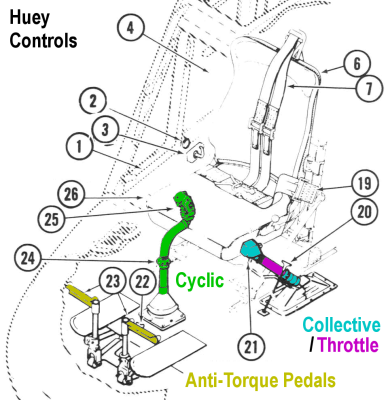
A helicopter primary controls include:
- Cyclic - similar to the joystick on an airplane, the pilot uses this control to change the direction and speed of flight.
- Collective/Throttle - the collective is a lever to the left of the pilot and the throttle is a twist-grip on the collective. The pilot uses these controls together to change the altitude of the helicopter.
- Anti-Torque Pedals - similar to the rudder pedals on an airplane, the pilot uses these to rotate the helicopter around the vertical axis.
The pilot uses the cyclic control to cause the helicopter to move longitudinally (forward and backward) or laterally (sideways).
Moving the cyclic control causes the main rotor to pitch and bank independently of the main body of the helicopter. This causes thrust to be deflected longitudinally or laterally which causes the helicopter to move in the opposite direction. The greater the pitch or bank, the greater the acceleration and speed in the desired direction.
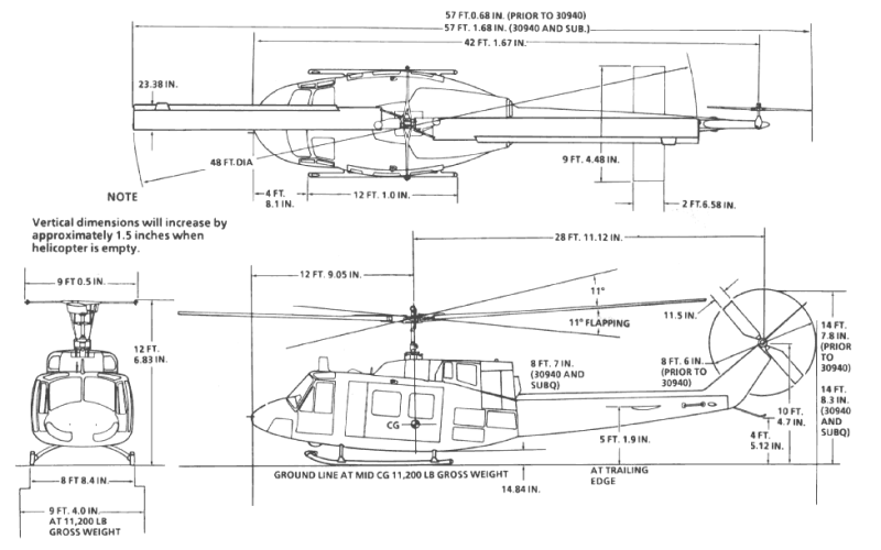
The Huey uses a "teetering rotor" mechanism to tilt the entire main rotor by up to 11 degrees, plus or minus. This allows the helicopter to accelerate from a hover. The main rotor shaft is also angled forward 5 degrees. On the ground, the shaft is vertical because the fuselage is angled back 5 degrees. The forward angle of the shaft, along with the teetering rotor creates a combined 16 degree forward pitch. This is enough to allow the fuselage to remain level at cruise speed (about 90 mph).
In the simulation, the cyclic control works essentially the same as on a real helicopter and activates an animated teetering rotor.
The pilot uses the collective/throttle to change the helicopter altitude.
Moving the collective lever changes the pitch of the blades to change "collectively", which changes thrust. At the same time, the pilot must adjust the power to maintain RPMs. Because these controls work in tandem, modern helicopters tend to link them together so that changes in the collective automatically change the throttle. But, on the Huey, these controls are separate.
In our airplane simulations, the user can change the power setting and the airplane will adjust to the appropriate speed. This is also a realistic way to simulate the operation of the collective/throttle in a helicopter. However, if the goal is to maintain a desired altitude, this will make flying a lot more difficult since the power required to maintain a certain altitude changes with both pitch and speed.
Consequently, in the simulation, we are using the control to set the desired altitude and we are assuming that your pilot persona will automatically adjust for required changes in power.
The pilot uses the pedals to control movement around the vertical axis. Almost every change in power requires a change in pedal pressure. This is because the power creates torque which tries to twist the helicopter around the vertical axis. Ideally, the pedal pressure will be roughly neutral when the helicopter is in forward flight.
In a real helicopter, hovering is one of the most difficult phases of flight because you must operate several controls in tandem. You use the collective/throttle to increase thrust and leave the ground. However, doing so, generates torque, which tries to rotate the helicopter around the Y axis. To counteract this tendency, you must press on the appropriate anti-torque pedal to increase the lateral thrust of the tail rotor. However, the lateral thrust of the tail rotor also tends to push the helicopter sideways. You must use the cyclic to bank the main rotor slightly to counteract this sideways thrust. You must adjust the collect/throttle to compensate for the resulting slight loss in lift. Etc. Changes in wind speed and direction require further adjustments. This is why learning to hover takes about 6 to 8 hours of practice.
While we could have added these complexities to the program, we assume that our users would not be interested in spending hours learning how to perform a simulated task. Thus, in our simulation, we are assuming that your pilot persona has mastered hovering - which is another way of saying we have not made any effort to add these kinds of complexities to the program.
In order to transition to forward flight, the pilot pushes forward on the cyclic. This pitches the rotor forward and deflects part of the downward thrust towards the rear. In a real helicopter, the pilot will also have to increase power slightly to compensate for the loss of lift. When speed increases to about 15 mph, the helicopter experiences "transitional lift" where the rotor begins to provide lift, like the wing of an airplane. This reduces the power required to maintain level flight. In both cases, the simulation will assume that your pilot will automatically adjust the power to maintain level flight.
The forward speed and acceleration depends on the forward pitch angle of the rotor. However, the further forward you pitch the rotor, the more power you need to compensate for the loss of lift. As speed increases, the drag increases. At some point, there is simply not enough power to do both - to overcome drag and to maintain level flight. In the case of the Huey, the maximum forward speed is around 140 mph.
The simulation will limit the forward pitch to insure that the helicopter does not reach the point where there is a decrease in altitude at top speed. However, since we want you to enjoy the fun of making a full pitch "military departure", the simulation will eventually allow for increased pitch at lower speeds.
The same principles should apply to level laterial (sideways) flight. However, the speed at which a helicopter can fly laterally is limited by a couple of factors. First, the drag when moving sideways is much higher than when flying backwards. This alone should significantly limit the maximum lateral speed. Second, even before reaching maximum lateral speed, the helicopter will start turning into the direction of flight (weathervaning). This can be counter-acted, but only up to a point, by the tail rotor.
The simulation models both factors. The simulation assumes that the increased drag moving laterally will limit the top lateral speed to around 40 mph. The simulation also forces the helicopter to rotate into the direction of flight above a certain speed. Thus, as with a real helicopter, the simulation allows the helicopter to move laterally at slower speeds.
One major difference between vertical flight and climbing flight is that less power is required to climb when the helicopter is moving forward. Thus, the operator of a fully loaded helicopter will often utilize a "running takeoff" where the operator will start running forward into the wind as soon as the helicopter leaves the ground.
As the helicopter gains speed, the operator will be able to start climbing. The power required to climb will continue to decrease as speed increases. However, at the same time, the power required to overcome parasitic drag will increase. In a Huey, the power avialable for climbing reaches a maximum at around 60 MPH. This is the "best climb" speed.
As with an airplane, there is a limit on how high a helicopter can climb. At higher altitudes, the air density decreases, which means that the thrust produced by the main rotor decreases. Eventually, the thrust will not be sufficient to overcome the constant pull of gravity.
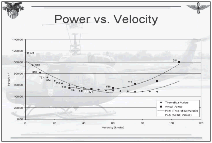
The chart most commonly used to show helicopter performance is the "Horsepower Used" chart. This shows the Horsepower (HP) Used at different speeds. This chart assumes that HP Available remains the same at all speeds. For the Huey UH-1H, the HP Available is 1400HP, or 1100HP for sustained operations. Consequently, the chart can be used to determine Net HP Available at various speeds. This excess HP can be used either to climb or to increase forward speed. The speed at which the excess HP is greatest is the speed at which climb performance is best. As the Chart shows, this speed is around 45MPH. The HP Used can be measured using instruments in the cockpit or can be estimated using a complex set of equations.
The estimation process generally breaks the HP Used into 3 categories:
-
Profile HP - HP used to overcome the frictional resistance of the main rotor blades passing through the air.
Induced HP - HP used to overcome induced drag created by the main rotor as it generates lift.
Parasitic HP - HP used to overcome frictional resistance of the helicopter moving through the air.
However, we don't need to concern ourselves with these details. Instead, we can simply used "curve-fitting" to create a single equation which yields a close approximation of the HP Used at various speeds.
As with our airplane simmulation, we will use a vector-based method which assigns an acceleration value to vectors along the longitudinal (foreward), vertical and lateral (sideways) axes.
A primary vector of interest is the maximum acceleration created by the main rotor. In the case of a propeller aircraft, we used an equation to convert horsepower to thrust force and we could convert that force to acceleration. However, the formula that we used does not work at low airspeeds. An alternative method is to estimate maximum acceleration, recognizing that the acceleration has to be sufficient to overcome the negative acceleration created by gravity. Based on the observed performance, we are using an estimated maximum acceleration of 1.5 X gravity. The gravity acceleration is 32.174 feet per second^2 which we will abbreviate as 32.174fps2. This means that the Huey maximum HP of 1400HP produces maximum acceleration of 48.26fps2. This is the assumed value for operations at standard air density at Sea Level and assuming a partly-loaded helicopter.
Pitching or banking the rotor will divert some of the downward thrust along the longitudinal or lateral axes. This will cause forwards, backwards or lateral flight. In level flight, the amount of thrust diverted (and, thus, the acceleration and speed) is limited by the angle of pitch or bank. Increasing total thrust will cause the helicopter to climb.
Computing the vectors for vertical flight is fairly straightforward. There are only 2 accelerations working on the helicopter and both are vertical: (1) the positive net rotor acceleration; and (2) the negative gravity acceleration. The negative parasitic drag is minimal and can be ignored.
We compute the net rotor acceleration by reducing the maximum acceleration by the acceleration used in excess of the amount needed to overcome gravity. The maximum acceleration is 48.26fps2. The chart above indicates that hovering uses 1100HP of the 1400HP available. Assuming a linear relationship, multiplying the maximum acceleration of 48.26fps2 by 1100/1400 yields an equivalent negative acceleration of 37.92fps2. Excluding the 32.174fps2 needed to offset gravity leaves 5.75fps2, which is presumably used overcoming induced and parasitic drag from the rotor. Thus, the net positive acceleration produced by the engine is 42.51fps2.
Thus, at ground level, the helicopter will start climbing at a rate of 10.34fps2 (42.51fps2 less 32.174fps2). This thrust acceleration will increase slightly while the helicopter is in ground effect and will decrease as the helicopter climbs by multiplying thrust acceleration by the air density ratio. We will mulitiply only the net rotor acceleration by these numbers since gravity remains unchanged.
Interestingly, these yield results which are roughly equivalent to actual values. For example, the maximum hover altitude for the Huey is 8200 ft. At that altitude, the density ratio is 78.14%. Multiplying 42.51fps2 by 78.14% yields a net rotor acceleration of 33.14fps2, which is just above the acceleration required to overcome gravity.
The forward thrust is produced by tilting the rudder forward. In level flight, the remaining vertical thrust vector exactly equals gravity. Thus, the difference between the HP used and the gravity is a horizontal vector. (If any part of the difference were used in a vertical direction, the helicopter would climb or descend.)
The primary force opposing forward thrust is parasitic drag, which is computed in the same manner as for an airplane. For a helicopter, drag acceleration = the flat plate area X dynamic pressure X speed / mass. The flat plate area for the smaller version of the smaller Huey is 19.5. We estimate that the flat plate for the UH-1H is 25. The dynamic pressure = air density X speed^2 / 2. The mass is 264.19 slugs.
From the chart, we know that the HP required for level flight changes with each speed. Using "curve fitting" we have created an equation that computes the approximate HP used at each speed. The equation is: HP used = 1103.045 - 27.88313 * MPH + 0.38164 * MPH^2 - 0.0011985569 * MPH^3. We can convert the HP used to acceleration used by multiplying the HP by the ratio of maximum thrust to maximum HP. For example, at the cruise speed of 95 MPH (doors closed), the HP used is 870.8. This equates to an acceleration of 30.02fps2. The difference between this number and the maximum acceleration available is the additional acceleration avaible for climbing. As the chart indicates, the speed at which the most acceleration is available is around 60 MPH.