 COMPUTING AIRCRAFT VECTORS
AND ORIENTATION
by Phil Crowther (revised 10/9/2020)
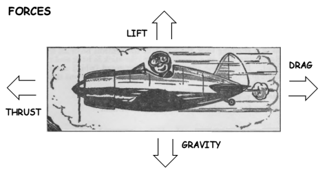
The primary forces affecting an aircraft in flight are thrust, drag, lift and gravity. To use these in a vector-based flight simulation, you must compute the acceleration for each vector. You can do that by, first, computing the Force for each vector and, then, dividing that force by the aircraft mass. You can use these acceleration vectors to compute the change in the Speed and Direction of Flight. You can use the resulting Direction of Flight to rotate the aircraft object and you can use the resulting Speed and Direction of Flight to compute the current map speeds, which you can then use to compute current map position.

You can compute the value of these vectors using different systems of units, including the US system which uses pounds (lb), feet (ft) and seconds (s); and the SI system which uses kilograms (kg), meters (m) and seconds (s). The basic equations are the same for both systems. You just need to take care that you are entering the correct values for that system. ACflyt can now use either US units or SI units.
See this worksheet for sample values and some basic computations.
The ultimate goal of the vector-based system is to compute Aircraft Speed and Direction of Flight so that you can rotate the aircraft object and map the position of the Aircraft within a traditional cube-shaped XYZ reference space. In this reference system, Z generally represents North, while X represents East and Y represents altitude.
The Direction of Flight is defined by the Aircraft vertical rotation and horizontal rotation. ACflyt assumes that the Aircraft is always pointed in the Direction of Flight. Consequently, the vertical rotation equals the Aircraft Pitch (ACPtch) and the horizontal rotation equals the Aircraft Heading (ACHead).
The first step involves using Aircraft Speed and ACPtch to compute the ZY Map Speed. The equations are as follows:
- Aircraft Z (Forward) Speed = Aircraft Speed * COS(Aircraft Pitch)
- Aircraft Y (Vertical) Speed = Aircraft Speed * SIN(Aircraft Pitch)
The second step involves using Aircraft Z Speed and ACHead to compute the ZX Map Speed. The equations are as follows:
- Aircraft Map Z (North) Speed = Aircraft Z Speed * COS(Aircraft Heading)
- Aircraft Map Y (Vertical) Speed = Aircraft Y Speed
- Aircraft Map X (East) Speed = Aircraft Z Speed * SIN(Aircraft Heading)
The final step involves adding the XYZ Map Speeds to the beginning XYZ Map Position to determine the ending XYZ Map Position.
The Aircraft will start with a given Speed and Direction of Flight. You must then compute the changes to Speed and Direction of Flight. ACflyt does so by dividing vectors into 2 basic groups, the Speed vector and the deflectors (Lift and Gravity).
The Speed Vector is the sum of the current Speed of the Aircraft +/- the Net Acceleration acting along the Direction of Flight. The Net Acceleration equals:
- The Acceleration Due to the Engine Thrust
- Less the Parasitic Drag
- Less the Induced Drag
- Plus or minus the acceleration due to Gravity acting along the Direction of Flight
The Lift deflector acts perpendicular to the Direction of Flight. As a result of Aircraft Bank (ACBank), this deflection creates both a vertical and horizontal deflection. The remaining Gravity (the part not included in the Speed Vector) creates a vertical deflection which reduces ACPtch.
The Thrust and Lift Vectors are initially computed as Force Vectors, which can be converted to Acceleration Vectors. The Gravity Vector does not have to be converted because Gravity is expressed as an Acceleration Vector.
In US units, Force is expressed in pounds (lbs) and acceleration is expressed as ft/s2. In SI units, force is expressed in Newtons (N) and acceleration is expressed as m/s2.
In the case of a propeller aircraft, Thrust will decrease with Speed. Thus, we use an equation that converts Engine Power to Thrust:
- Thrust = Engine Power * Prop Effectiveness(n) / Speed (V)
- Engine Power = the power of the engine. In US units, this equals the horsepower X 550 lb_ft/s. In SI units, this value equals Watts.
- Prop Effectiveness (n) = the effectiveness of the propeller in converting Engine Power to Thrust. This value can range from roughly .7 to .85.
- Speed = the speed of the aircraft. This value is ft/s in US units and m/s in SI units.
In contrast with a propeller-driven aircraft, the thrust for a jet aircraft is fairly constant. As a result, we do not have to solve for Thrust, but can use a published value for Thrust.
For ACflyt, you enter the aircraft values in the data file. You can enter values for either a prop or a jet. ACflyt will make the appropriate computation for Power. In your program, you can vary the thrust by changing the ACPowr from 0 to 1. You can also add an afterburner to a jet. It will be engaged when ACPowr is 1.
The Thrust vector is oriented in the direction that the aircraft is pointing. For simplicity, ACflyt assumes that the aircraft is pointed in the direction of flight. In most cases, this is a fairly safe assumption since they will generally only diverge by a few degrees.
Two common components of the equations for Lift and Drag are Dynamic Pressure(Q) and Wing Area(A). The equation for Dynamic Pressure is:
- Q = 1/2 * Air Density (p) * Speed2 (V2).
- Air Density (p) = a value which represents the density of the atmosphere. This number varies with altitude and temperature. Most computations use standard sea level values of .002378 slugs in US units and 1.225 kg/m3 in SI units.
- Speed2 (V2) = the speed of the aircraft expressed in (ft/s)^2 in US units and (m/s)^2 in SI units.
The Wing Area is a constant value which is different for each aircraft and is expressed in ft2 in US units and m2 in SI units.
With that preface, the equation for Lift is:
- Lift = Dynamic Pressure (Q) * Wing Area (S) * Coefficient of Lift (Cl)
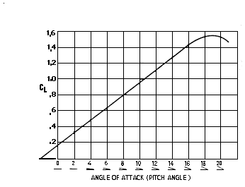
The Cl is a variable that generally ranges from about +1.6 to -1.6. For most aircraft, the Cl is about 0.1 * Angle of Attack (AoA). In simple terms, the AoA is the difference between the angle of the wing and the direction of flight. In real life, the pilot changes the AoA by changing the aircraft pitch. However, ACflyt shortcuts the process by allowing the pilot to change the Cl directly. (See discussion of Lift and Angle of Attack in the Design Notes below)
The resulting Lift vector is generally oriented perpendicular to the direction of flight - or, from the perspective of the pilot, straight down (or up if the value is negative).
An aircraft generates Lift by angling the wing relative to the angle of flight (the AoA). This causes the wing to generate drag, known as Induced Drag (DragI).
The equation for Induced Drag is:
- DragI = Dynamic Pressure (Q) * Wing Area (S) *Coefficient of Induced Drag (Cdi)
The equation for Cdi is:
- Cdi = Coefficient of Lift (Cl)2 / (Aspect Ratio (A) * Wing Efficiency (e) * PI)
- Aspect Ratio (A) = Wingspan2 (b2) / Wing Area (S)
- Wing Efficiency (e) = A constant that generally ranges from .7 to .75
This vector is oriented in the opposite of the direction of flight.
Parasitic drag (DragP) or Zero Lift Drag is the Drag caused by movement of the aircraft through the air. The equation for Parasitic Drag can be expressed as follows:
- DragP = Dynamic Pressure (Q) * Wing Area (S) * Coefficient of Drag (Cd0)
- Cd0 = a constant value that varies for each aircraft and for each aircraft configuration.
This vector is oriented in the opposite of the direction of flight.
The Cd0 is different for each aircraft. The Cd0 might be .0404 for a WWI biplane (Fokker D-VII), .0211 for a WWII aircraft (Grumman F8F) or .0172 for a jet aircraft (F-104G Starfighter).
The Cd0 also varies with the configuration of the aircraft. For example, where an aircraft has retractable landing gear or flaps, the Cd0 will be significantly greater when the landing gear or flaps are down. The Cd0 value that is generally given is for an aircraft in clean configuration.
When searching for the Cd0 for your aircraft, you may notice a great deal of variation in the values. Part of the reason is that researchers might compute Cd0 by reference to the Wing Area, the Frontal Area or the Total Wetted Area of the aircraft. We are using Wing Area because that appears to be the most common and is used to compute Lift and Induced Drag.
|
Note that this approach may cause some confusion because these reference units may have no necessary relation to the Parasitic Drag. For example, if you have 2 aircraft with equal parasitic drag, the aircraft with the larger wing area will have a lower Cd0. But the lower Cd0 does not necessarily indicate that the aircraft is more streamlined, merely that it has a larger wing area. Ideally, the Cd0 would simply be given in "raw" undivided form. But that would force you to figure out why Cd0 values differ for different aircraft. The reasons could be physical size, better "streamlining", or the actual or hypothetical area in contact with the airflow. For example, automobile designers learned that a cut-off "Kamm" tail was not significantly worse than a more streamlined-looking "boat" tail. Aircraft designers found that a "coke bottle" shape was more efficient for transonic and supersonic flight (the "Area Rule"). |
You can test the Cd0 by comparing the computed maximum speed of the aircraft at sea level to the published value. (Using the sea level values is important because changes in altitude can introduce many other variables into the equation.)
Once you have computed the Force vectors for Thrust, Lift and Drag, you can compute the acceleration vectors by using the equation Acceleration = Force (F) / Mass (m). In US units, mass is computed using the equation: Mass (m) = Weight (W) / Gravity (g). This gives the value of mass in slugs. In SI units, Mass is given in kg.
The Acceleration Vectors are expressed in ft/s2 in US units and m/s2 in SI units.
Because they operate in the Direction of Flight, you can combine the Thrust and Drag Vectors into a single Net Thrust Vector. You can then add the Net Thrust Vector to the Aircraft Speed to determine the new Aircraft Speed. Since the Lift and Gravity Vectors are deflectors that act in different directions, they are kept separate.
We break the Gravity Vector into two parts. The first part of the Gravity Vector is the portion which acts along the Thrust Vector and is added to or subtracted from the Net Thrust Vector, depending on the Aircraft Pitch. The second part of the Gravity Vector is treated as a deflector which deflects the flight path downward.
ACflyt assumes that the aircraft is pointed in the Direction of Flight. Thus, the values for Direction of Flight are stored in the rotation.x (ACPtch) and rotation.y (ACHead) values for the aircraft object. (The rotation.z (ACBank) value does not affect the Direction of Flight.) Once we have computed the Vectors for Speed, Lift and Gravity, we need to compute the changes in the Direction of Flight due to Lift and Gravity. The direction of changes due to Gravity is simple. Since the second part of the Gravity vector operates only downward, Gravity will change only the rotation.x (ACPtch) value.
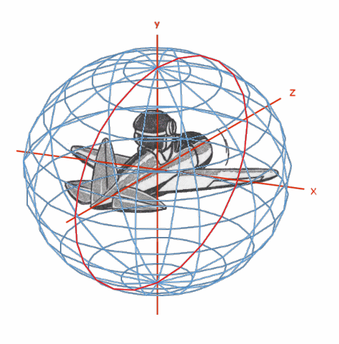
However, computing the direction of changes due to Lift is more complicated. Lift operates vertically with respect to the aircraft. Thus, the change in Direction of Flight will be affected by both aircraft pitch and bank. Furthermore, changes in pitch relative to the aircraft will cause changes in bank. This is because aircraft pitch and Lift works within a Spherical Reference System.
You must compute the degrees of deflection caused by Lift and Gravity. Where as here, the deflection causes the object to change direction, we can use the following equation:
- Change in Radians = Accel / Speed
- Change in Degrees = (Accel / Speed) * (180 / PI)
This gives the change in direction along an arc, which has a radius equal to Speed and where Accel is the distance travelled along the arc.
You can plug the degrees of deflection for Lift into PPPtch and ACflyt will compute the resulting change on ACPtch and ACHead. The degrees of deflection for the portion of Gravity not offsetting Thrust will change ACPtch directly and will not change ACHead or ACBank.
To compute the result of changes in the Aircraft-related Pitch, we must use a Spherical reference system, as illustrated below:

In this reference system, the Aircraft-related Pitch acts along a "Pitch Plane" which is banked relative to the horizon. The Aircraft-related Pitch along this plane is the Pitch Plane Pitch (PPPtch). The angle of the Pitch Plane relative to the horizon is the Pitch Plane Bank (PPBank). The Pitch Plane Heading is the horizontal heading offset from the place where the Pitch Plane intersects the horizontal plane. You can also use these values to compute ACPtch and ACBank. You make these computations using the Napier equations developed for use in computing values for spherical right triangles.
You can convert the values in the Standard reference system to corresponding values in the Spherical reference system. To recap, the primary variables in the Standard reference system are:
- ACBank - Aircraft Bank - relative to the horizon (obj.rotation.z)
- ACPtch - Aircraft Pitch - relative to the horizon (obj.rotation.x)
- ACHead - Aircraft Heading (obj.rotation.y)
The primary variables in the Spherical reference system are:
- PPBank - Pitch Plane Bank - relative to vertical.
- PHBank - Pitch Horizontal Bank - relative to horizontal.
- PPPtch - Pitch Plane Pitch - relative to the Pitch Plane intersection with the Equator
- PPHead - Pitch Plane Heading - relative to the Pitch Plane intersection with the Equator
- PPHOff - Pitch Plane Heading Offset - the difference between PPHead and ACHead
All of these variables have a range of 0 to 360 degrees, except for ACPtch which has a range of +/- 90 degrees. (But note that the obj.rotation values must be entered in radians.)
ACflyt starts with the values for PPBank, PPPitch and ACHead. Thus, when initializing the program you need to compute initial values for PPHead, PPHOff, ACBank and ACPtch. The equations we use are, in the following order:
- PPHead = DEGREES(ATAN(COS(RADIANS(PHBank))*TAN(RADIANS(PPPtch))))
- PPHOff = ACHead - PPHead
- ACPtch = DEGREES(ASIN(SIN(RADIANS(PHBank))*SIN(RADIANS(PPPtch))))
- ACBank = DEGREES(ACOS(SIN(RADIANS(PHBank))*COS(RADIANS(PPHead))))
These equations generally use PHBank, instead of PPBank. PHBank equals 90 degrees - PPBank. PPBank equals 90 degrees - PHBank.
In addition, because these equations only work in a limited range, you need to adjust the results. This requires that the sphere be divided into 16 zones. They are numbered using the following conventions:
Ref PPBank PPPtch 01 000-090 000-090 02 000-090 090-180 03 000-090 180-270 04 000-090 270-360 05 090-180 000-090 06 090-180 090-180 07 090-180 180-270 08 090-180 270-360 09 180-270 000-090 10 180-270 090-180 11 180-270 180-270 12 180-270 270-360 13 270-360 000-090 14 270-360 090-180 15 270-360 180-270 16 270-360 270-360
One of the most difficult challenges has been to determine the dividing line between sectors. This is further complicated where you are using a formula that contains the TAN function which has an upper range of infinity. In many cases, we had to use trial and error.
Determining the sector from ACBank and ACPtch is more challenging because the range of ACPtch is only +/- 90 degrees and ACHead is ambiguous. To overcome this limitation, we computed sectors based on the old sector and the nature of the change - assuming that the change will only cross one sector.
In ACflyt you do not change the pitch of the aircraft directly. Instead, you change the Coefficient of Lift, which changes the Lift and causes the aircraft to change direction along the Pitch Plane. This change in direction causes changes to ACHead, ACPtch and ACBank. To compute all these changes, you must already have the value for PPBank - which does not change as a result of changes to PPPtch. To compute the new PPPtch, you simply add the degree change caused by Lift to the old PPPtch.
The equations we use are essentially the same as above - except that ACHead changes:
- PPHead = DEGREES(ATAN(COS(RADIANS(PHBank))*TAN(RADIANS(newPPPtch))))
- ACPtch = DEGREES(ASIN(SIN(RADIANS(PHBank))*SIN(RADIANS(newPPPtch))))
- ACBank = DEGREES(ACOS(SIN(RADIANS(PHBank))*COS(RADIANS(newPPHead))))
- ACHead = ACHead + (newPPHead - oldPPHead)
In contrast, with Pitch, you change the Aircraft Bank directly. This change affects ACBank (obj.rotation.z), but does not change ACPtch. Conversely, Gravity affects ACPtch (obj.rotation.x) but does not change ACBank. Thus, to save steps, you can compute these changes before computing the new Spherical reference values. For each, you will compute the change and the new reference number (if any). After than is done, you can compute the new values for PPBank, PPPtch and PPHead. None of these changes will affect ACHead. Thus, ACHOff will change by the amount of the change to PPHead.
The equations we use are as follows:
- PHBank = DEGREES(ACOS(SIN(RADIANS(newACBank))*COS(RADIANS(newACPtch))))
- PPHead = DEGREES(ATAN(TAN(RADIANS(newACBank))*SIN(RADIANS(newACPtch))))
- PPPtch = DEGREES(ACOS(COS(RADIANS(newPPHead))*COS(RADIANS(newACPtch))))
- PPHOff = PPHOff - (newPPHead - oldPPHead)
In an aircraft, Lift is generated by pitching the aircraft backwards or forwards in order to create an angle between the wing chord and the direction of flight. The vertical difference (relative to the aircraft) between the wing chord and the direction of flight is the Angle of Attack (AoA). The AoA is what generates the Lift - the greater the AoA, the greater the Lift - up to a maximum of around +/- 16 degrees. Beyond that, the airflow will separate and the wing will "stall" (similar to how a car tire skids sideways in a turn when the tire loses traction). To recover from the stall, you must pitch the aircraft forwards (generally) or backwards, until the AoA is again in the acceptable range.

You use the AoA to compute the Coefficient of Lift (CfL). This will vary for each wing shape. However, as illustrated above, the CfL appears to be roughly 1/10 of the AoA.
Typically, flight simulatons compute Lift using the AoA, which requires them to keep track of both aircraft orientation and flight orientation. However, in ACFlyt we simplified matters by having the user input the CfL and to have the program compute the resulting change in flight direction and orientation. Since the relationship between AoA and the CfL is linear, we could "back into" the AoA and adjust the aircraft orientation.
But instead of making a second set of calculations, we found that you can use an animation to show Aircraft Pitch. The animation simply pitches the aircraft back or forward depending on the AoA. To avoid having to fly "nose up" all the time, we reduced the pitch by the "Angle of Incidence" (AoI). This is the amount of pitch built into the wing so that, in cruise flight, the aircraft is flying level.
If you have flown in an aircraft, you will have noticed that banking the aircraft in level flight causes the aircraft to turn while the aircraft remains in level flight. You can thank Gravity for this result. In the absence of Gravity, you would turn by looping up and then down.
Although you may not have noticed, when the aircraft was banked, the pilot had to pull back on the controls to generate the Lift required to maintain level flight. This is because, when the aircraft is banked, the amount of Lift required to counteract the downward pull of Gravity increases, as shown by the following equation:
- Required Lift = Gravity / COS(Aircraft Bank)
But, for our purposes, the more interesting result is that some portion of this Lift is directed horizontally. This causes a change in Aircraft Heading. The rate of turn can be computed using the following equation:
- Rate of Turn = TAN(Aircraft Bank) * Gravity / Aircraft Speed
Because additional Lift is required to counteract Gravity, some of this Lift is directed horizontally and creates horizontal rotation.
We considered several ways to handle this complication. For example, we considered breaking the Gravity vector into 3 parts - the Gravity acting along the Direction of Flight; the Gravity acting along the Pitch Plane; and the Gravity acting along the Yaw Plane. However, the equations for computing Yaw are fairly lengthy. In the end, we opted for the easier approach of treating the portion of Gravity not acting along the Direction of Flight as a vertical vector. This does not require you to make additional computations because you can combine it with the Bank computations.